

RF and Microwave Course Syllabus

Introduction to RF and Microwaves
- Spectrum of RF and Microwave Frequencies
- Frequency bands and Regions of Spectrum Allocations
- Time and Frequency Domains
- Fourier series and Fourier Transform
- Modulation (Heterodyning) and Frequency-Shifting
- The Decibel for Power Ratios
- Summation of Voltages and Mean Power
- Representation of Power-Voltages dBm, dBW, dBµV/m
- Motivation for Wireless (Radio) communication
- Modeling Lumped and Distributed Components at Radio Frequencies

Noise in Communication Systems
- Introduction
- Classification of Noises and Thermal Noise
- Power Spectral Density of Noise
- Band-Limited Noise, Amplitude and Phase Noise
- Noise Factor and Noise Figure
- Matching the Noise Figure to Input Noise Level
- Noise Temperature
- The Notion of Excess Noise
- Noise Factor of an Attenuator, Divider, Combiner
- Noise Factor of a Cascade
- Sensitivity
- Noise and Sensitivity of a Receiving RF Chain Cascade
- Measurement Methods of Noise Factor
- Noise and Sensitivity Performance with Antennas, G/T
- Design-Rules for minimizing System Noise
Non-Linearity Phenomenon
- Introduction and Non-Linearity Phenomenon
- Spurious Signals
- One-dB Compression Point
- AM/AM and AM/PM below and into Compression
- Representing a Memoryless Response by a Power Series
- Harmonic Stimulus: Single and Tow-Tones – Intermodulation
- In-Band and Harmonics Spectrum
- 2nd and 3rd Order Intercept Points
- Spurious-Free Dynamic Range (3rd Order IM’s) SFDR3
- Characterizing Non-Linearity of a Cascade of Blocks
- Measuring Non-Linearity
- Design-Rules for minimizing System Non-Linearity

Performance Optimization of RF Chains
Propagation of EM Waves
- EM Waves
- The Atmosphere and Classification of its Layers
- Characteristics of the Wireless Path (Channel)
- Free-Space Propagation of Waves – Friis Equation
- Link Budget and Free-Space Path Losses
- Effective Isotropic Radiated Power – EIRP
- Line-of-Sight (LOS) above Earth
- Path Loss for Communications over the Horizon
- Propagation in Urban Regions – HATA Models
- Log-Normal Shadowing and Shaow-Margin (Numerical Example)
- Indoors Communications – Measurements and a Computational Model
- Waves Propagation over Flat Earth
- Point-to-Point Communications with an Obstacle – Diffraction (Fresnel)
- Rayleigh (fast) Fading and Fade-Margin
- Doppler Effect
- Scattering and Reflection (Radar Cross Section – RCS)
- Ground-wave Propagation (Ranges vs. Frequencies)
- Sky Waves, Day/Night Frequencies
- Microwave Links, Ray Bending in Atmospheric Propagation
- Ducts, Tropospheric Propagation
Transmission Lines and Distributed Systems
- Introduction to Transmission Lines and Familiar Examples
- Lumped and Distributed Systems
- The Telegraph Equations and the Waves Solution
- The Wave Equation – Forward and Reverse Waves
- Characteristic Impedance and Propagation Velocity
- The Load (Relative to Zo) Effect on the Reflected Wave
- Types of Transmission Lines (Coaxial, Conductor-Pair, Printed – Microstrip, Stripline)
- Standing-Wave in a Transmission-Line
- Reflection Coefficient and Voltage-Standing-Wave-Ratio (VSWR)
- Efficiency of Power-Transfer
- Terminations (Source and Load) of Transmission Lines
- Short, Open, and Matched Loads’ Impedance as viewed at the end of a Variable-Length Transmission Line
- Reflection Parameters
- Transmission Parameters
- Wave representation of Two-Port and the S-Parameters
- Phase Velocity
- Group Velocity
- Dispersion
The Smith Chart and Load Matching
- Smith Chart – Impedance on the reflection plane
- Review of Transmission Lines and normalized impedances (by Z0)
- Display of Smith Chart – Constant Resistance and Reactance Circles
- Presenting Admittance in the Smith Chart
- Numerical Examples
- Fixed SWR Circles
- Finding the Impedance seen into a Loaded Reactive Circuit
- Impedance Matching – L, Π, T, Sections, Transmission Lines and Stubs
- Bandwidth of Matching Networks
- Quarter Wavelength Transformer
Transmit and Receive Architectures
- Heterodyne and Super-Heterodyne Receiver
- Intermediate Frequencies, Image Frequency, Heterodyning with/without Spectral Mirroring
- Input Band Filtering of Interference and Noise at Image Frequency
- An Example of an FM Receiver
- Transmission and Reception via Direct Conversion – In-Phase and Quadrature (I-Q) Mixing
- Design Considerations for an RFIC transceiver
- Software Defined Radio (SDR)
Spectral Analysis
- Signals in time and Frequency Domain
- Types of Spectrum Analyzers
- Basic Block Diagram of an Analog SA
- The SA as a Receiver
- Selectivity, AGC, LO Phase Noise
- Microwaves Spectrum Analyzer
- Frequency Resolution and RBW
- Limitations on the Sweep Rate
- RF Attenuator
- IF Amplification
- Shape Factor of the RBW Filter and Sweep Rate
- Noise Floor
- Video Signal Filtering (Post-Detection)
- Filtering by Averaging Screens
- SA Controls (Span, RBW, Att, VBW)
- Dynamic Range
- Detector Types and their Characteristics
- Sampling and the Sampling Theorem
- Spectrum of a Uniformly Sampled Signal
- Artifacts in Digitally Processed Spectrum Display
- Side-Lobes in Frequency Domain and Windowing
- RBW broadening by Windowing
- 2nd and 3rd Order Distortions and Spurii – Identification of Saturation in the SA
- Effect of LO Phase Noise
- Residual FM
- Time Domain Measurements – Zero Span
- Signal Power response in time
- Intermodulation Measurements
- Intermodulation with two-tones Stimulus
- Adjacent channel power (ACP)
- Adjacent channel leakage ratio (ACLR)
- Tracking Generator Configuration and Scalar Network Analyzer Measurements
- Demonstration of SA operation and Measurements
RF and Microwave Passive Devices
- Active and Passive Devices
- Active: Amplifiers, Frequency Sources, Mixers, Antennas
- Passive: Filters, Duplexers/Multiplexers, Antennas, Mixers, Couplers, Dividers/Combiners
- Power Dividers and Combiners – Coherent, Incoherent and Partial Summation
- Isolators and Circulators
- Phase Shifter
- Attenuators, T and Π Pads
- Cables and Coaxial Connectors
- Switches
- S Parameters of Passives (Unitary Property for Lossless Passives)
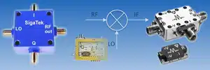
Mixers
- What’s a Mixer?
- Frequency Shifting – Up- and Down-Conversion
- Simple Diode Mixer
- Double Balanced Mixer
- Performance Parameters of a Mixer
- Isolation
- 1 dB Compression
- VSWR
- Conversion Loss
- I/Q Mixer Imbalance
- Effect of Imbalance on EVM
- Sub-Harmonic Mixing
Filters
- Characterizing Filters
- Bandwidth
- Quality Factor
- Passband Insertion Loss
- Ripple
- Group Delay and GDV
- Shape Factor
- Prototype Normalized Response
- Chebyshev Filter
- Butterworth Filter
- Bessel Filter
- Eliptic Filter
- Determining the Filter Order
- Implementation Examples: Lumped Case
- Implementation Examples: Printed Case
- Additional Implementation Technologies: Resonators, YIG, Coaxial, Dielectric
Frequency Sources and Synthesizers
- Objectives and uses of Frequency/Clock Sources
- Classical Oscillators, Quartz and SAW Oscillators
- Voltage Controlled Oscillators (VCOs)
- YIG Oscillators
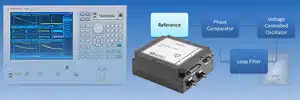
- PLL Based Synthesizer
- Basic PLL
- Basics of a PLL Synthesizer
- Analog PLL Synthesizer
- Multi-Loop Synthesizer
- Digital Synthesizer – Direct Digital Synthesizer (DDS)
- Phase Noise
- Phase noise of a Crystal Source, of a VCO
- Phase Noise in a PLL Synthesizer
- Calculating Jitter from Phase-Noise Measurements
Vector Network Analyzer
- Introduction to the Network Analyzer
- Measurement Types Performed by the VNA
- Scalar and Vector Network Analysis
- Review of Transmission Lines
- Transmission and Reflection Parameters
- S parameters
- Construction of the VNA
- Coupling to the Measured Signals
- Detection Types
- Dynamic Range
- T/R Setup versus S-Parameters Measurements
- Types of Measurements Errors
- Basic Error Models and Calibration
- One-Port and Two-Port Models
- Review of Calibration Methodologies for Minimization of Errors
- Measurements Review – Power Sweep for AM/AM, AM/PM, and Harmonics
- Time Domain Measurements (TDR)
- Demonstration of VNA operation and Measurements
Digital Modulations
Introduction/basic concepts-
Digital Communication System
-
Coding Rate
-
Eb/No – The Normalized SNR
-
Digital Modulation Types
-
Digital Modulation Signals
-
Received Complex Envelope
-
Digital Modulator
Digital Modulation with Single Waveform (QAM)- PSK-Phase Shift Keying
- ASK-Amplitude Shift Keying (PAM)
- QAM (square grid) -Quadrature Amplitude Modulation
- APSK
- Variations of QAM
- Receiver for Single Waveform Modulation
- Matched Filter, Correlator, Nyquist Theorem
- QAM performances: Waveforms, Spectrum, BW, Probability of error
Digital Modulation with M Orthogonal Waveforms-M-OK-
Pulse Position Modulation-PPM
-
Walsh Hadamard
-
MFSK
-
Transmitter
-
Coherent/Non Coherent Receiver for M-OK
-
Performances: BW and Probability of error
-
Multiple Access Methods
Introduction- Resource Allocation
- Duplexing
- Multiplexing
- Multiple Access
Time DivisionFrequency DivisionCode Division- Frequency Hopping
- DS Modulation
Random AccessApplications and design considerations- Frequency Division Duplexing – FDD/Time Division Duplexing – TDD
- CDMA vs. Time division and Frequency Division
OFDM, OFDMA
Multi-Carrier methods- Orthogonality concept
- Orthogonal frequency-division multiplexing – OFDM
- Orthogonal frequency-division multiple access – OFDMA
- Transmitter / Receiver implementation
OFDM characteristic- Cyclic prefix
- OFDM Waveforms
- OFDM Spectrum
Design Considerations and Applications- Multicarrier Technology Advantages
- Fast Scheduling and Link Adaptation
- Throughput Maximization by Adaptive Transmission
- Implementation in LTE
PAPR – peak-to-average power ratio PAPR Mitigation Techniques
Antennas
- The Role of the Antenna
- Review of EM Waves in Space and Matching in Transmission Lines
- The Antenna Characteristics
- Frequency Range
- Antenna Directivity and Gain
- Antenna Pattern
- Polar Pattern Display
- Cartesian Pattern Display
- Beamwidth
- Main Lobe and Side-Lobes
- Front-to-Back Ratio
- Antenna Aperture
- Polarization of EM Waves
- Polarization Types: Linear (Vertical, Horizontal) Circular
- Far-Field Range
- High-Level Review of Basic Antennas
- Half-Wave Dipole
- Dipole over a Back-screen
- Corner Reflector
- Ground Plane and the Monopole
- Slot Antennas
- Long-Wire Antennas
- Loop Antennas
- Helix Antenna
- Yagi Antenna
- Broadband Antennas (Logarithmic, Spiral)
- Horn Antenna
- Printed Antennas
- Microstrip Antenna
- Fractal Antennas
- Short Backfire Antenna
- Antenna Arrays
- Phased Arrays
- Adaptive Arrays
- Parabolic Reflector Antenna
- Converting Balanced and Unbalanced Lines (Baluns)
- Radomes
- DAS – Distributed Antenna Systems
- Antenna Measurements
- (Far and Near-Field Measurements)
RF and MW Design with Simulation Software-CST
- Introduction & Built-In Help
- Basic Modeling
- CST MICROWAVE STUDIO Solver Overview
- Ports, Materials & Boundary Conditions
- Result Handling & Template-based Postprocessing
- Optimizer Overview
- Workflow Example 1: Microstrip – Quarter-wave Transformer
- Workflow Example 2: Printed LPF filter
- Homework: Wilkinson Power Divider

Demonstration and Hand-on of Practical Measurements
Spectrum Analyzer (SA) – Measurements Demo- Parameters and Measurement types of the SA
- Resolution and Video Bandwidth
- Attenuation and Scaling
- Channel Power
- Adjacent Channel Power
- Sensitivity and Noise Floor: Dependence on RBW, ATT, Improvement with LNA
- WCDMA signal Peak-to-Average Power (PAR) Measurements
- Time-Domain Measurements on Zero Span of a Pulsed Periodic Signal
- Demo of Heterodyning – Sum and Difference Frequencies, and Leakages
Vector Network Analyzer (VNA)– Measurements Demo- Setting Up and Calibrating the VNA
- S11 of an Antenna
- S11 of a Variable length Loaded Transmission Line
- Power Sweep Measurements of an Amplifier and Displaying AM/AM, AM/PM and Harmonics
- Filter Response including Amplitude, Phase and GDV
- Response of a Differentiator
Vector Signal Analyzer (VSA) – Measurements Demo- QPSK Signal Demo: EVM, Eye-Pattern, Eye-Opening, PAR, Spectrum
- Same as above with Additive Noise
- I/Q Mixer Modulation Demo, Demonstration of the Image Rejection
- OFDM Signal Spectrum, Time0Gated Spectrum of Sections of the Symbol